Hi John
I’m close to the result i think. Could you check why this code fails. The payload result is not working as i assume the send is wrong but I don’t know why. I write out the .json file but it’s empty so i expect the error. I don’t know why the file is empty as i thought these json payloads would work.
Regards
Paul
json_loop.py (1.4 KB)

The port is incorrect (should be 8000) and the property name for the username is “user” when logging in.
1 Like
Hi John
Thanks for finding my mistakes ![]()
Looking so hard at it I couldn’t see the obvious copy paste errors.
All working now. Cheers. I’ll share the full project when done. Just waiting for a couple more LED displays to arrive.
Cheers
Paul
1 Like
Glad I could help, Paul! I’m excited to see what you came up with ![]()
1 Like
Hi John
Got it all formatted and displaying on the LED displays great. just working on the LED display loop now. If I debug step through the code it’s fine but fails after maybe three loops on the tm1637 command when I run normally. Some GPIO thing I need to sort out. Again, all kind of new to me me. Should be completed in a day or two. Golf games getting in the way of hobbies at the moment. ![]()
Cheers again for your support.
TP
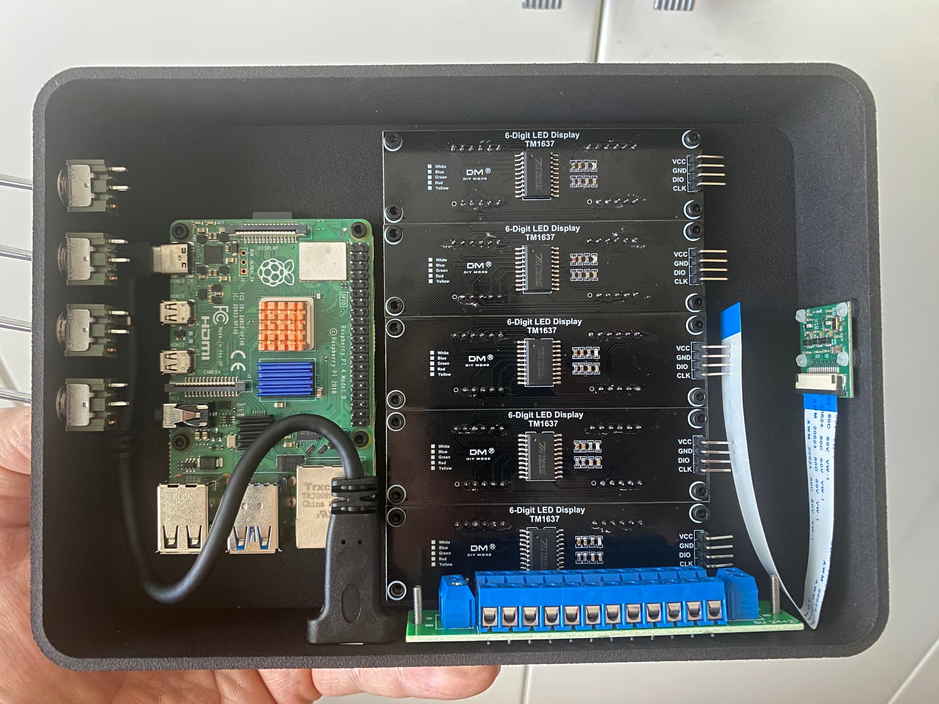
Hello John
This is what I have so far. Just waiting for the other LED modules to arrive and will make a case etc to package it. I’ll share the code and details once I add some comments and clean it up a bit and take out all the testing stuff.
Cheers again for your help.
TP
1 Like
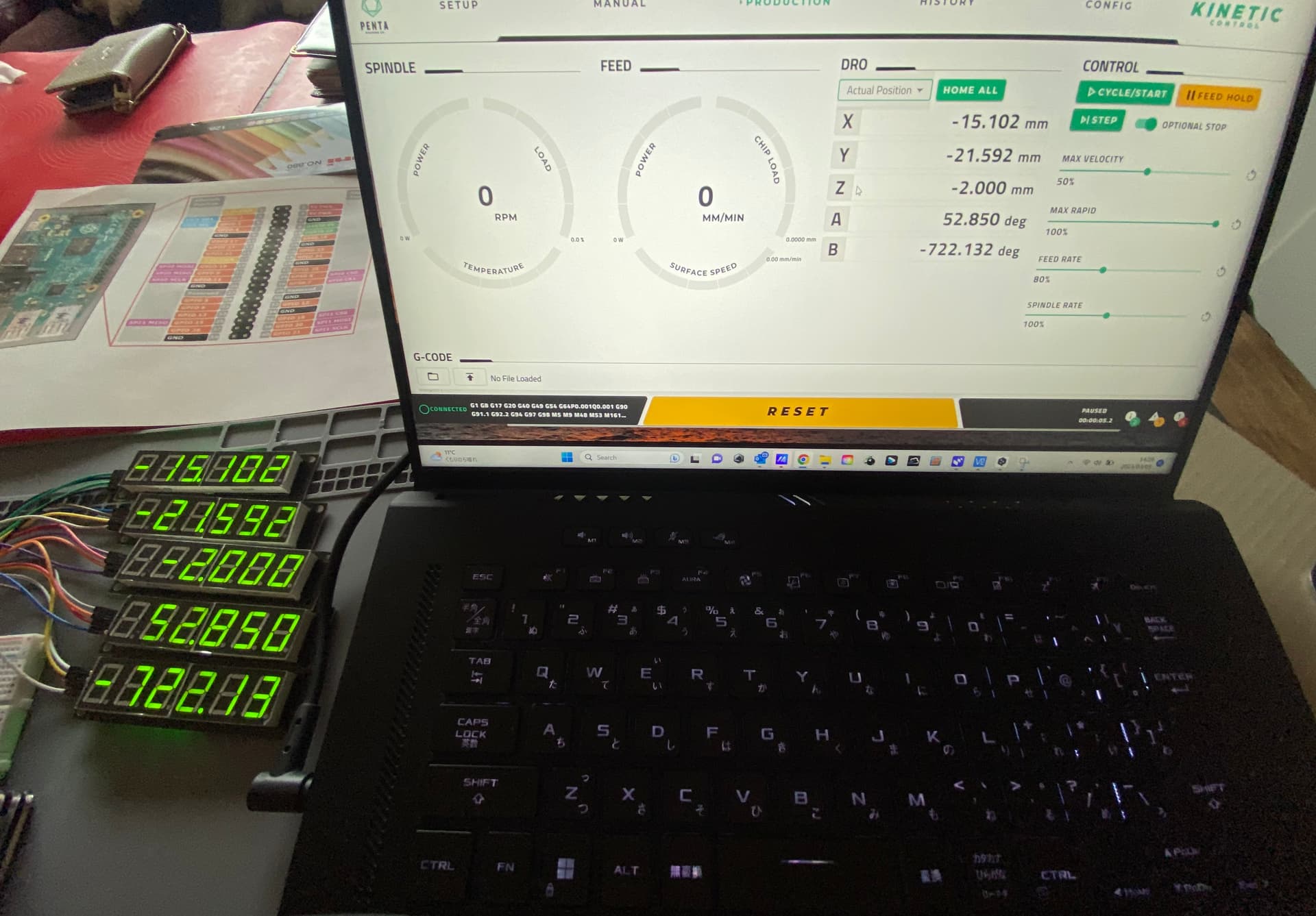
And B axis which is the one I don’t have a great solution for as the B axis can realistically go to a signed 4.3 digit number but I can only display a maximum of 6 of the 8 possible. I guess I’ll just drop off the 2nd and third digits only happens on program execution and not a big deal. Jogging is usually limited to +/- 360 or maybe 720 to dial things in. I may just programmatically limit it to show +/- 360. Haven’t decided yet.
Anyway, all working in each axis.
1 Like
Looking great @TokyoPav! I think dropping a couple digits would be a reasonable solution for B. You may also have a negative sign, so that would take off another digit sometimes. Alternatively, you could try scrolling through the digits.
Unfortunately the scroll call doesn’t work with the 6 digit implementation of this module without a lot of work. The tm1637 is an extended 4 digit module so lots of stuff doesn’t work. Even had to dig deep into the tm1637 module to find a hidden class just to get this far. ![]()
Quick update for John. I got the DTG values working so I’ll put a toggle switch on the panel to switch between actual position and distance to go with a signal to a gpio pin.
Still waiting for some more LED displays to arrive. The batches I received are slightly different colour so 4 more of each on the way. Just need to wire it all up for testing then make a case.
It’s been a handy project so far to understand the websocket interface.
Cheers
TP
1 Like
Hardware and software working.
I change the number formatting of the b axis display based on the current value. +/- numbers all have different formatting. Seems to be the best solution. Physical switch coded in to change the display from actual to distance to go. In the video I switch from dtg to actual.
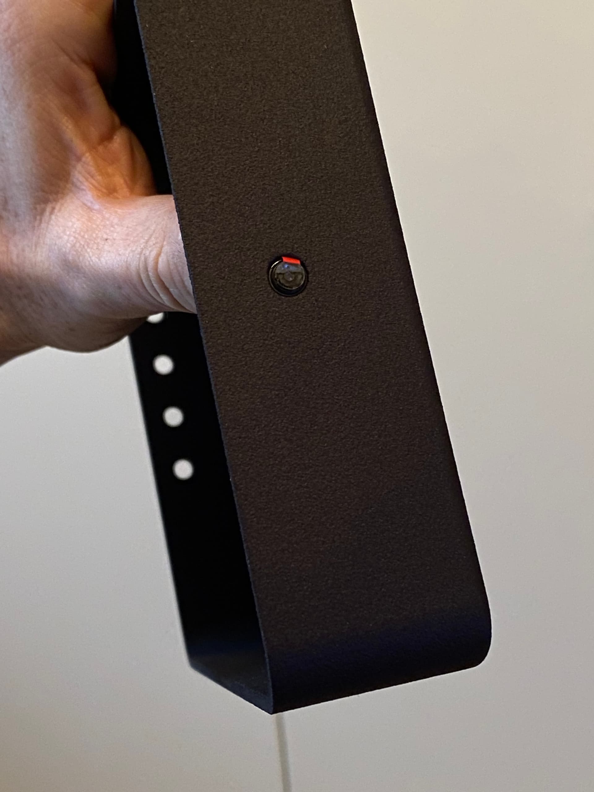
Just designing a case now and will also have a pi camera inside so can watch remotely.


1 Like
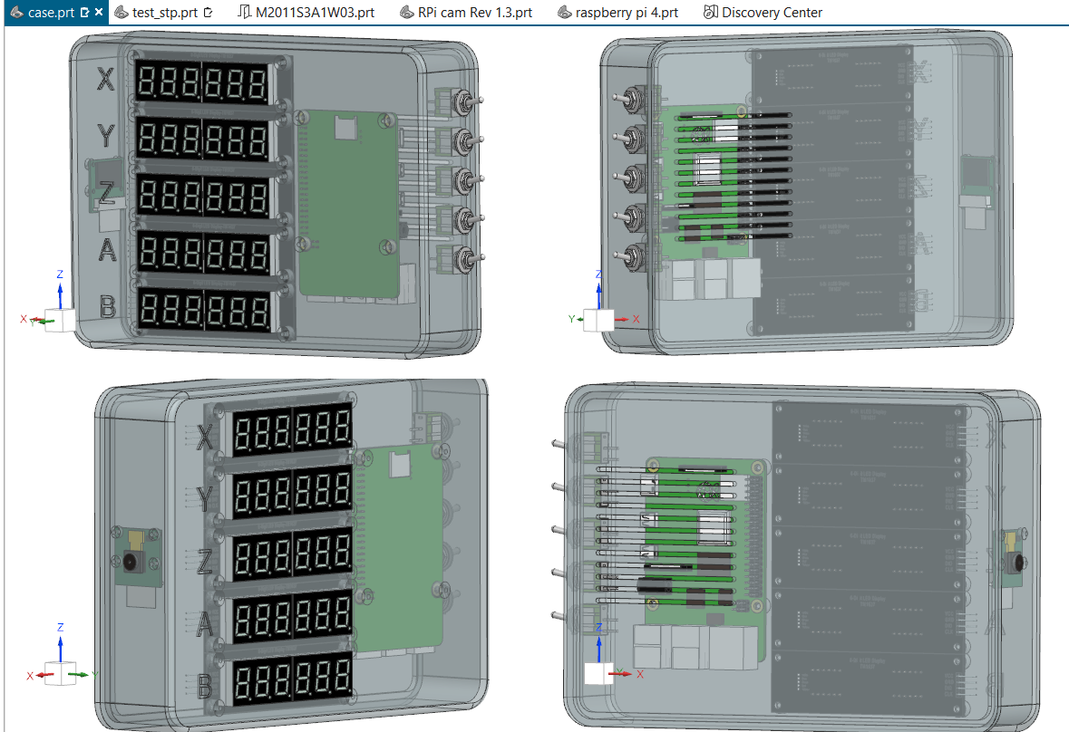
Rendering of the case I’m getting 3D printed. Additional switches for Inch/Metric conversion and maybe something else. Future proof
1 Like
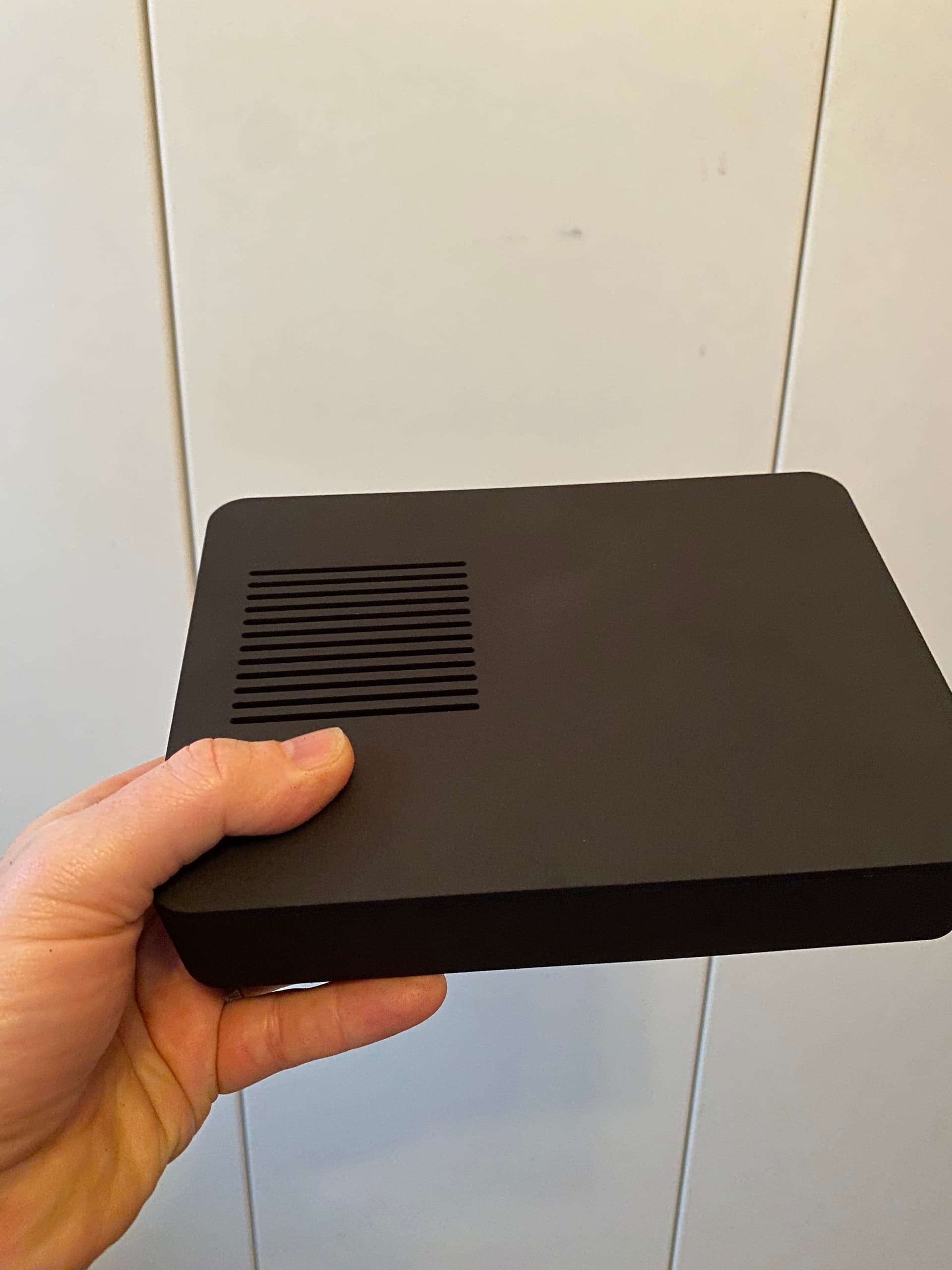
3D printed case arrived. Test fitting spare LED modules and pi camera. Will complete the build next week. I’ll add a metric / imperial switch to the code and case as a final tweak.
I’ll share all the code and 3D models for those who are interested after the build. I had the case printed through Shapeways.


1 Like

That’s incredible! Great work! Once I get a machine I’ll have to make one of these!
I get the desire to have X Y and Z and even A on a DRO, but I can’t fathom how to make good logic of the A and B axis readouts combined.
It seems like a B axis move would kind of ruin the knowledge of the positions of the other axis?
Maybe I’m not thinking right…
–Matthew Schroeder
1 Like
That’s the kinematic calculations. The post(at least in NX) knows the distance from center of B axis to center of A axis then it just some highschool maths to work out the rest.
The DRO I made is reading the values from the machine itself.
Cheers
TP
Got the RPI camera up and running, streaming the work area now. The DRO is now mounted on a small tripod so it can be positioned or raised/lowered as needed. It’s become quite the exercise in many aspects. ![]()
1 Like
This looks awesome. I’m getting my machine prob next week should be here!
1 Like
I’ve made some significat changes to the homebrew DRO.
I’ve updated the script to properly subscribe to the websocket to get correct display update performance. I also optimised the coordinate routines. I’ve added a program timing function by activating the second toggle switch on the side of the case. With the 2nd switch up it displays normal coordinate mode that can display position(up) or disance to go(down). When the 2nd switch is down it changes the display to show various machine times. When the 2nd switch is toggled down the 1st switch will behave as a timer reset.
Timer Mode (Switch 2 DOWN):
- X: Total job time (elapsed since start)
- Y: Feed time (G1/G2/G3 cutting moves)
- Z: Rapid time (G0 rapids)
- A: Program time (Y + Z, excludes pauses)
- B: Pause time (X - A)
If anybody is interested in this project please reach out I’ll be happy to help.
DRO_V4_README.md (4.9 KB)
dro_v4.py (7.4 KB)
DRO_V4_QUICKSTART.md (6.0 KB)
DRO_V4_WIRING.md (6.2 KB)
Regards
TP
2 Likes