Struggling with coordinate systems in NX

I’ve spent the last few months learning enough Siemens NX (build 3701) to be dangerous and reading through other’s experiences on using NX CAM with the Pocket NC. I feel like I’ve consumed all the bits of info available for making NX work with a Pocket NC, but I keep running into strange coordinate system issues.

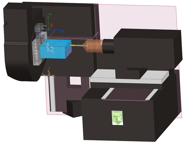
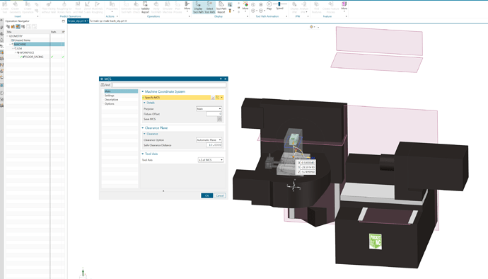
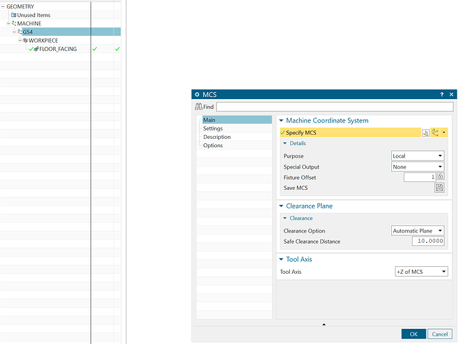
I’m just trying to do a floor operation on the top of the part. I’m using the machine kit available from post hub (version 5.5.0). The Geometry has a MACHINE MCS located at the machine’s origin, and a G54 MCS located on the stock touch off point. Both are oriented with Z pointing towards the tool, Y up. But when I bring the Gcode over to Kinetic control and simulate it, modifying the G54 Z moves the simulation up/down. I’m honestly at a loss and I’m not sure how to debug it further.

MACHINE MCS

G54 MCS

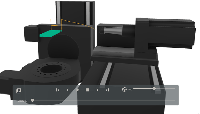
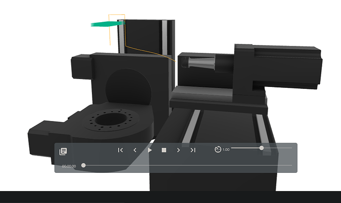
Machine Code Based Simulation

Penta Simulator with correct G54

Penta Simulator with G54 Z set to 100mm

Gcode
jaw.ngc (5.0 KB)

I’d really appreciate any help

HI @littlepumpkin
When I test and set my TLO to -82.682 in setup (the current setting for the tool loaded in my machine) it looks ok.
What is your setting for TLO on T15?
regards
TP

Also, the height difference you are seeing between the last two images is correct. Remember its a 5 axis machine so the motions before Z will be to orient the A axis so the tool axis is 90 degrees to what the images show so the actual tool path is moving along the Z axis once its done the orientation move.

If you can share the NX part file I can check the setup and test on my machine.

Hi Tokyo, I’m glad you’re still hanging out in the forum :slight_smile:

This is probably just me fundamentally misunderstanding something. When I create the both MCS they’re with Z pointing towards the spindle with A=0 and B=0. When I’m touching off the part it’s also with A=0,B=0. When I perform the facing operation, I was expecting it to know as part of the operation (to make the toolpath normal to the face) it’d rotate A to 90, but it’d handle Y/Z swapping correctly. Currently if I put a longer tool in the device, and touch off, it makes the toolpath go lower on the Y axis, instead of away from the spindle as I expected.

I could change the G54 to point Z upwards, and the toolpath locates correctly then, but I can’t get A to rotate 90.

I’m not sure that made sense? I could record a video going through it or something like that if it might help understand the issue?

If you send your part file I’ll set it up as reference for you and make a video. We can also have a video call if needed and I can explain live with your part. I also think you moved the G54 csys in x and y away from the center of the B axis. That will move the program unless you put the XY shift in the G54 setting in the Kinetic UI under setup.

Hey @littlepumpkin, I’m somewhat familiar with the coordinate systems but I use Fusion 360 and don’t have any experience with your software - so you’ll have to try and join the dots as best you can…

I’ll say a few words about rotated coordinate systems and then I’ll get on to your issue, just to make sure the ground work is covered.

[In Fusion 360] When creating a Setup, the WCS can be chosen by the user as G54, G55, G56, etc. When posting the tool paths, under the multi-axis section, the default dumping ground for the rotated coordinate SYSTEM (RCS) is G59.3 (Fusion 360 default - you’ll see why in a bit). Imagine that your program has a load of different tool paths with the A & B tables at all different angles, each time they rotate for the next operation, the trigonometric relations for any WCS offsets are dumped into G59.3, so G59.3 gets overwritten over and over again. For this reason, Fusion won’t let the user choose G59.3 as a WCS if its also the RCS. Assuming all this makes sense, then let’s move on.

Consider when A = 0° & B = 0°, we set a WCS offset as Z=+0.2mm (ie to the right when looking at the main table). Now consider a tool path that simply requires A to be 90° - this ‘right direction’ is now straight down, ie Y=-0.2mm.

To reiterate, I would go into the Penta interface and set my WCS offsets in there. I leave G54 as all zeros since multiple users use the Pocket NC and most software defaults to use G54. But we have a custom plate which bolts to the B table with a pattern of dowel pin holes and after many, many careful measurements, it turns out that this plate has a rotational offset of 0.12° clockwise that cannot be corrected by loosening the screws and rotating etc and there’s some small X & Z offsets too. So under G55, we currently have X=0.05, Z=-0.15, B=0.12°. However when I made the measurements, A was set to 90° so my measurements were actually in X & Y. The X offset stays as is (so long as B = 0°), but +Y becomes -Z. Hopefully this helps get the penny to drop for you. Cut out a small arrow and a big arrow out of paper and use bluetac to stick these to the table pointing up/down and left/right. Then in the Midi, type G0 A90, and then G0 B90, and see what directions the arrows end up pointing.

One thing thats worth mentioning is that in Fusion 360, all our Setups have the origin as the true origin of the machine (where the A table axis crossed in space with the B table axis) and so we just position parts in the software where they are on the machine. So our WCS offsets are all just small tweaks.
1 Like